Reporting Parameters
Reporting parameters in Revit are great, particularly if you are a structural engineer. They give you access in the family to things that you have no way of defining within the family. The best way to explain is with an example.
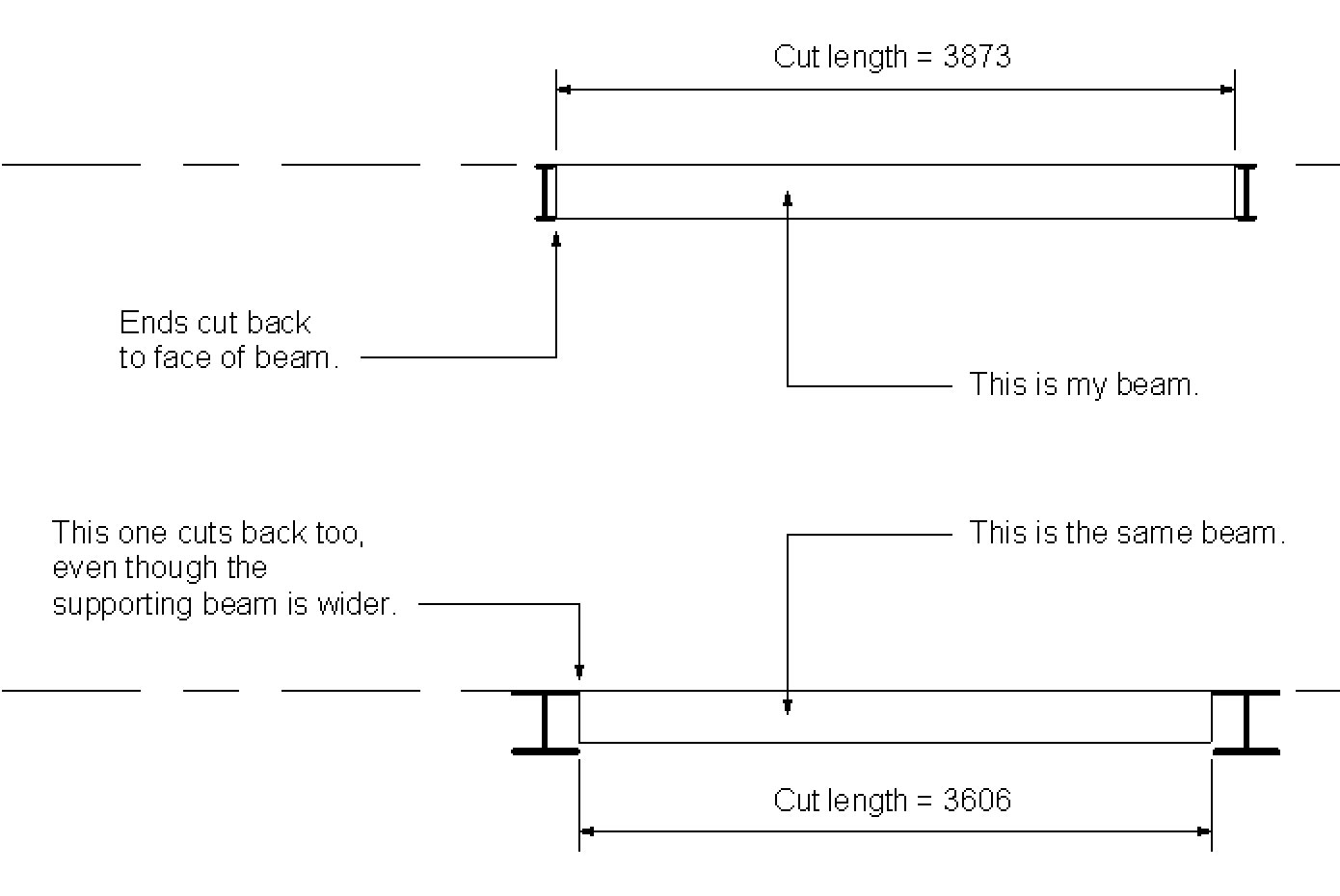
When you view structural framing in Revit, the ends of beams will automatically cut back according to how wide their supporting beam is. This all happens because of the ‘Member Left’ and ‘Member Right’ planes which exist in the standard structural framing family template.
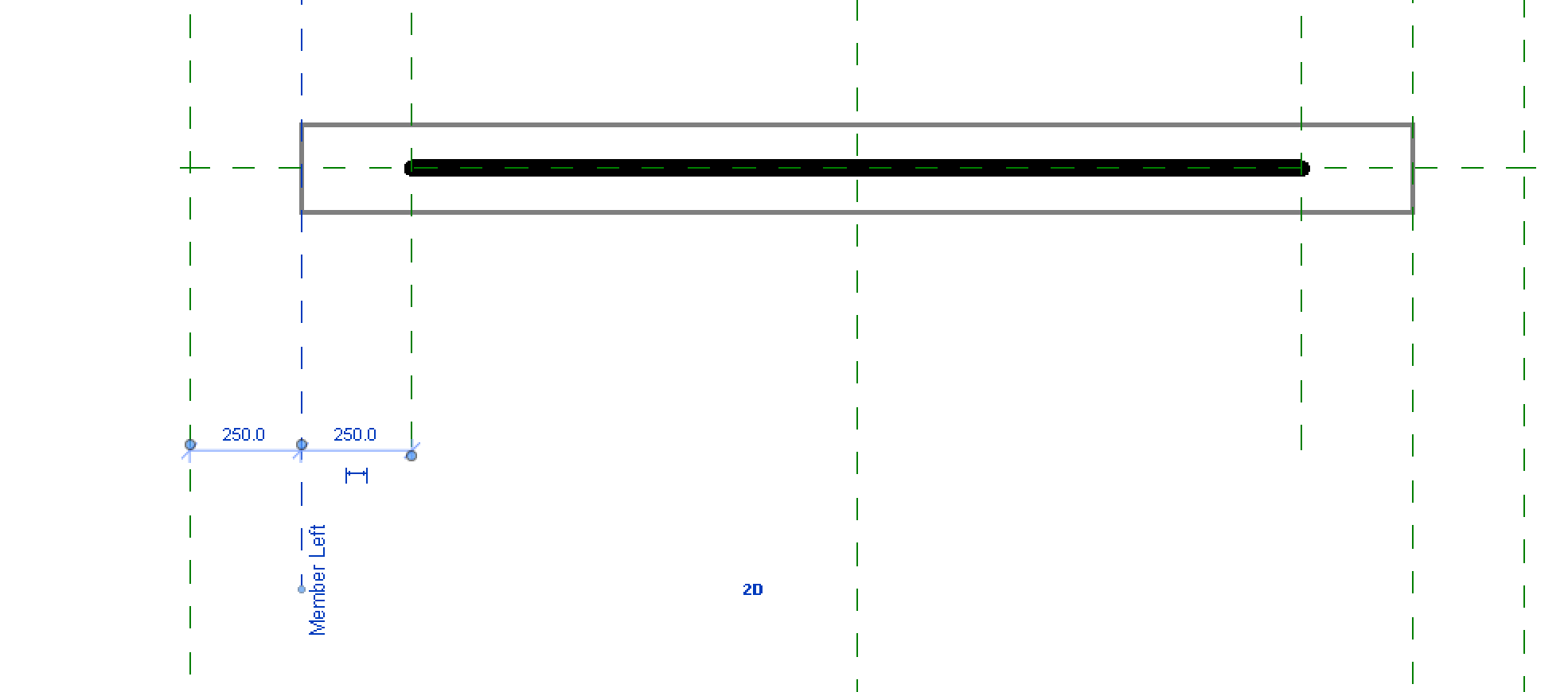
This is the most simple structural framing family that you can make.
When we put this into a project spanning between two supporting beams it works well. The ends cut back according to how wide the supporting beam is. This is great. You can also see that it gives us access to how long the actual ‘cut length’ of the beam will be.
We can add some parameters into our structural framing to make it a bit more interesting. I have made it deeper for the middle third and tapering for each of the ends. I have fixed the ends to the ‘Member Left’ and ‘Member Right’ planes to ensure I keep my nice cut back.
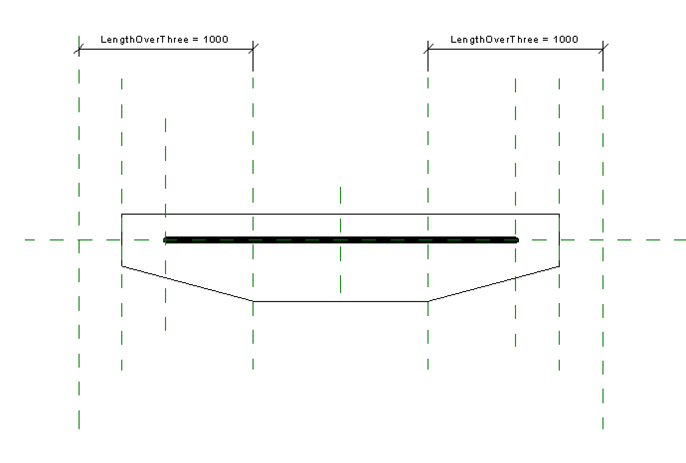
When I put this into the project it works well. My beam is tapered for the first and last thirds and deep in the middle. Perfect.
Now what I would like to do, is take advantage of this cutback distance. I want to use it in some calculations. And I can do that by using a reporting parameter to dimension between my ‘Member Left’ plane and the ‘Left’ plane, and the same on the other end. To show you what I mean, here is a snapshot of the family. Take my word for it that these are reporting parameters (it doesn’t work if they aren’t either). I haven’t actually used these reporting parameters for anything yet, but I plan to use them to do something clever like give my beam a prescribed amount of bearing on its support.
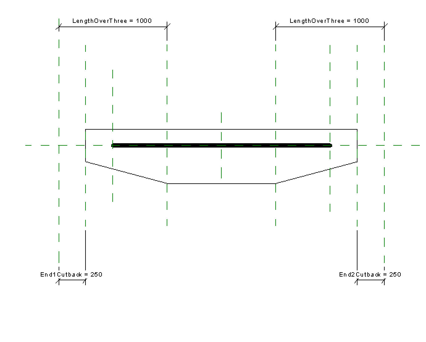
When we load this back into our project, something rather bizarre happens.
The beam will correctly insert with its tapered ends at third points when you first insert it. But if you subsequently change the location of the supporting beams and increase the span, the length of the tapered bits stays the same rather than maintaining its one third relationship. Even more confusingly, if I look at the ‘LengthOverThree’ parameter in the properties dialog box it is reporting the correct value, not the one shown on screen. Now I’m confused.
If you don’t believe me. Try it for yourself.
The solution
I did eventually discover the solution to this problem. Though it took me rather longer than writing this post! If you add a reporting parameter to the length of the beam and use this in ALL of your calculations instead of the native ‘Length’ parameter the problem seems to go away.
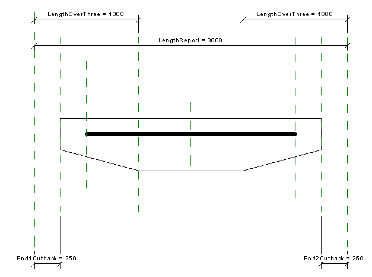
I don’t know why this happens. I have a theory that it might have something to do with the length as a parameter within the family. After all, ‘Length’ isn’t really a normal parameter, it must be a reporting parameter. How can the family know how long the beam is going to be until it’s placed?!
Please give me a shout if you come across this issue in any other circumstances or find another way around it!
Tate Extension
Every time I head to Allies and Morrison’s offices in Southwark I walk past the new extension which is being built for the Tate Modern on London’s Southbank. With its slightly peculiar shape and large amount of concrete walls, at first I wondered whether it might be a disappointment for what has become the most visited art museum in the UK.

But as it’s grown it’s turned into a real winner, in my eyes at least. The cladding is modern, yet blends in perfectly with the existing; it appears solid, yet provides an immense amount of light for the gallery space contained within; and it different, intriguing and special, without detracting at all from the surroundings, or the many exhibitions which will be contained within it over then next few decades.

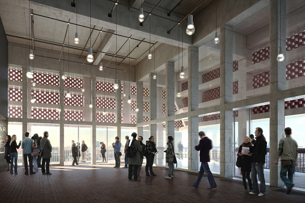
Image courtesy of http://www.bocadolobo.com/
I’m not quite sure about the corner detail though….

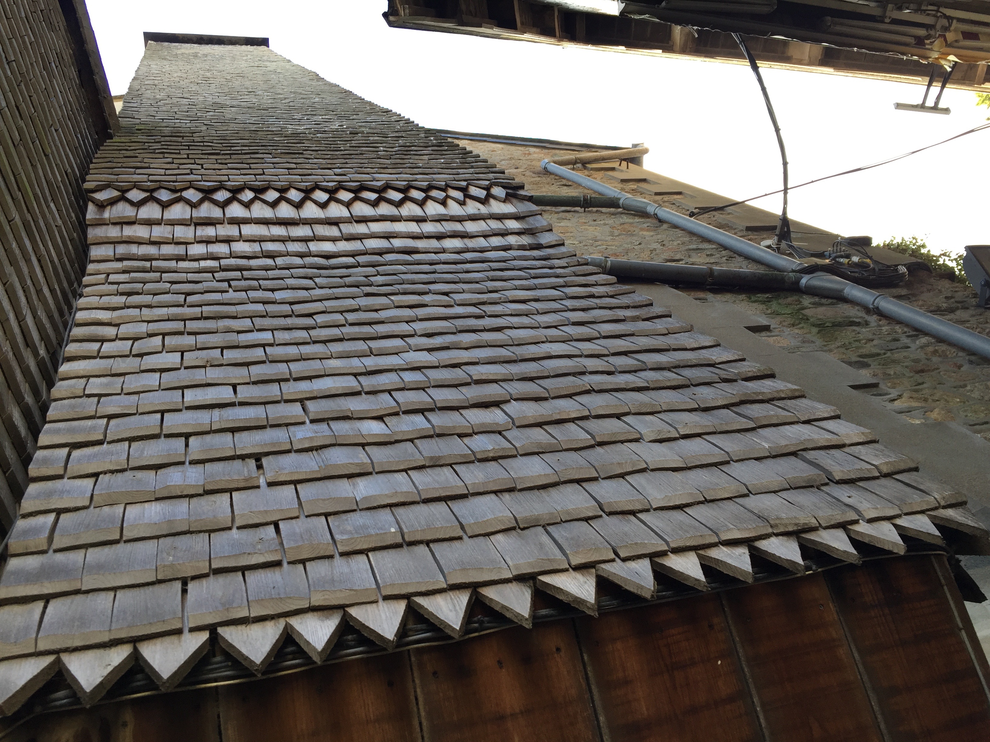
Mont Saint Michel
I can’t help but feel like I’ve entered Harry Potter’s world today.


I love the timber shingles which clad these buildings.

An Analogy
I bake bread. Sometimes my bread is pretty great, sometimes it’s a rock hard pancake of disappointment. A while ago, I decided that it was partly down to how I measure the ingredients. Perhaps the mechanical scales which I bought for £0.99 from Asda a decade ago aren’t as accurate as they once were.
For my birthday, in March, I was given some shiny digital scales which measure to an accuracy of one gram. It’s now July. In this time, I have baked many loaves and rolls. Some have been good, many have not, but I didn’t use my new shiny scales as they needed to be mounted on the wall and I didn’t get around to it and, well, I’m quite attached to my Asda scales – I’ve had them for years, I know them, I like them, they are familiar and comforting. They remind me of the many cakes I baked (and ate) at university.
Last weekend, I finally got around to installing my new scales. It turned out it wasn’t as difficult as I thought to put them up*. I have since made several great loaves and even some pretty good rolls, without a single disaster.
What is the point of this? I hear you cry. Well, all of you Revit users are sitting here reading this with a computational design package already installed on your computer. You’ve probably heard of Dynamo. Have you spotted the icon in your Add-ins tab? You might be frightened of the world of computational design, you might be happy with your current methods and workflows, you might even produce some pretty good results sometimes. But couldn’t it be better? Couldn’t it be simpler, faster, more efficient?
Now, I’m not suggesting that your successes and failures are merely down to chance, as with my rather dubious scales. What I am suggesting is that just because you’ve been doing something in a particular way for a while it doesn’t mean that you shouldn’t try something new. Experiment with a new tool, or a change in your workflow. Try using Dynamo to link Revit to Excel, or to draw some geometry, or to harvest some data. Who knows, it might be the best decision you ever made!
If you’ve never used Dynamo before, check out this post to get you started.
* for the record – I am currently cooking in a rather temporary kitchen with crumbly, lime rendered walls with cement patches, so fixing to the walls isn’t as easy as you might expect – I’m not just pathetic!
My First Dynamo
You’ve heard of Dynamo, you’re keen to learn more? Then read on!
Lists
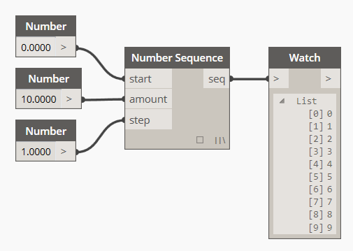
Dynamo is all about lists. They can be lists of room numbers, or lists of column sizes or just plain lists of numbers.
Here is a list of numbers:
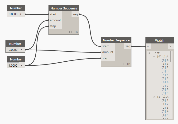
What about a list of lists?
Let’s make it useful. You can create a list of room data and write it to an Excel file. If you can’t find any of the files in the Node Library just type the name of the node (e.g. “All Elements of Category”) into the search bar at the top of the Node Library.
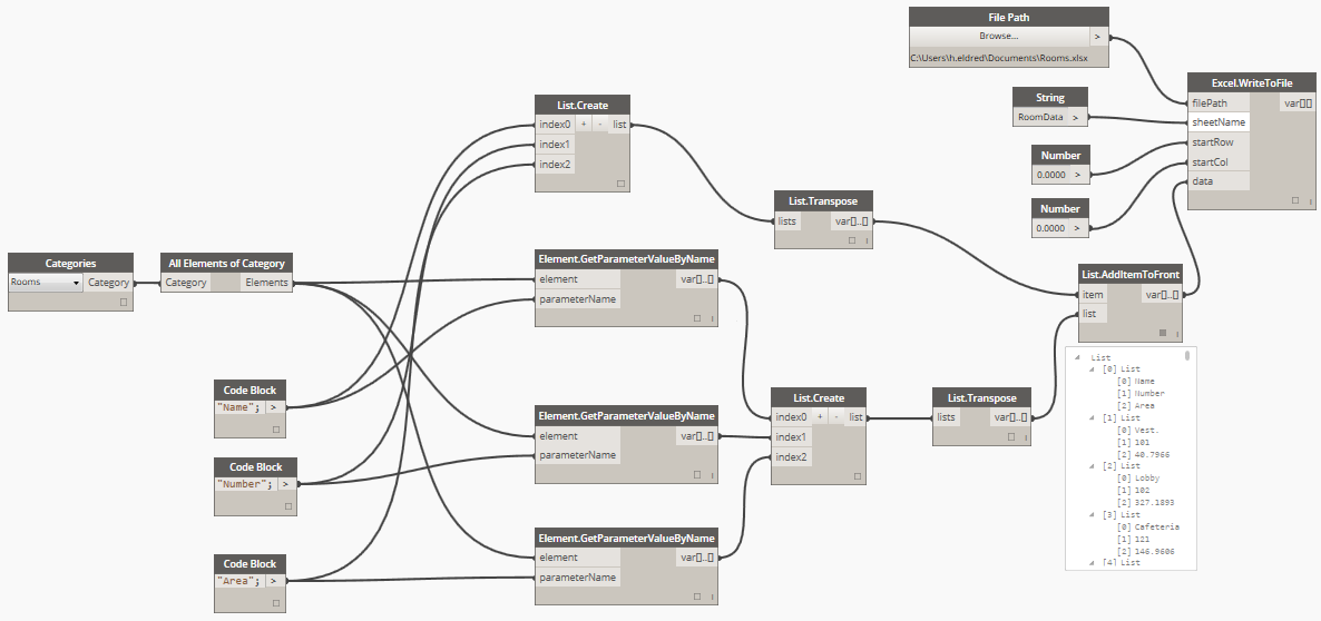
Here is a gif of the process in action. Go on… give it a try! (Click for a larger version)
Check back for more soon…
Revit and facades
Part of my role involves creating new training material which will be delivered by my fellow CASEians to companies all over the world. I love this part of my job as it involves delving really deep into Revit and working out the best way to deliver training to people with varying levels of experience.
This time, my focus has been on facade systems – curtain walls, curtain systems, pattern based facade systems and adaptive components.

Using Dynamo Code Blocks to create lists of numbers
Love them or hate them, Code Blocks in Dynamo can be exceptionally powerful, but working out all of the different syntaxes is nearly impossible. So here’s a list of the ones that I know about. Please leave a comment if you know any more!
I’m not going to go into using functions and calling nodes from a Code Block, but there are lots of options here too. Check out the links at the bottom of the post.
You can do all of these either in a Number node or in a Code Block. The result is the same.
Create a list of numbers
The first one is simple – create a list of numbers. The syntax is:
StartValue..UpperBound
This will create a list of numbers starting at the StartValue and increasing in steps of 1.0 until it reaches the UpperBound. Note that we’re using an upper bound rather than an end value – you wont necessarily get the upper bound value as a number in your list, depending on the values you pick…
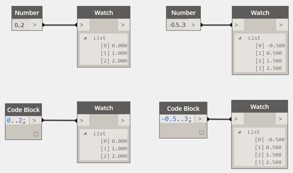
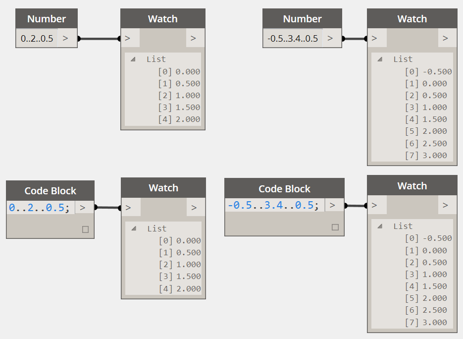
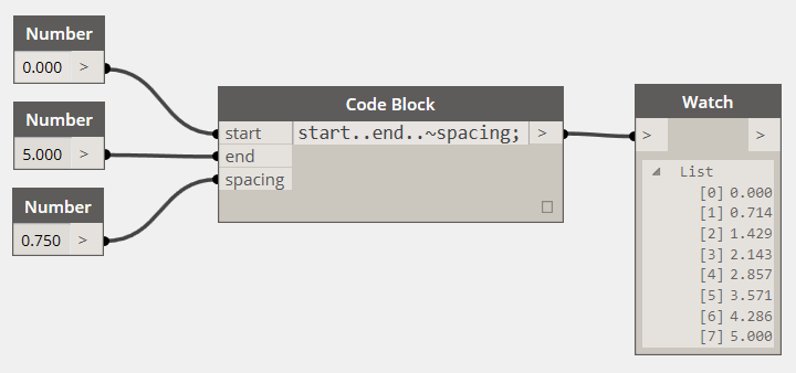
Number list with custom spacing
You can change the step size in your list of numbers by adding an extra bit to the end of the syntax:
StartValue..UpperBound..StepSize
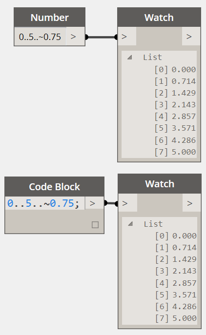
List of approximate values
What if you want to make sure you hit your end value, but you aren’t too bothered about whether the step size is exactly as you have input. No problem, you can use this syntax to get the closest available match. This will adjust the spacing to hit your end value exactly:
0..5..~0.75
What if you want to use sliders?
Everybody loves sliders, no problem. Replace any or all of the values with a string to extract it as an input.
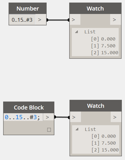
Create a number list with a start and end value
In this option you get to specify the StartValue, the EndValue and the NumberOfValues you want. The syntax goes like this:
StartValue..EndValue..#NumberOfValues
But what if you want MORE?
This is just the tip of the iceberg when it comes to what you can do with a Code Block. There is a great post about Code Blocks on the Dynamo website. Check it out and get creative!
Finally, if you’re really keen, check out this link to the Dynamo Language Guide.
BIM and why we should focus on the ‘why’…
A short time ago I was fortunate enough to attend the second annual CASE Retreat in San Francisco (you can read about what we got up to here: CASE takes SF). We came from all corners of the globe and descended on San Francisco for four days packed with fun, ideas and an exceptional amount of inspiration. However before we all left the comfort of our home offices, we were encouraged to watch this TED talk by Simon Sinek, and I would encourage everyone to make time to watch this too. Do it soon.
You might be wondering why this is relevant to engineering, or structures, or BIM, or… well… anything, but this is the whole point. Remember those days of blissful peace before clients were writing BIM requirements into your scope and you didn’t care what BIM was, in fact you’d probably never heard of it?
If I had come up to you and said something like this:
I believe that there is huge potential to streamline the design process to allow us to build better, more efficient buildings.
I’m pretty sure you would have agreed with me and immediately jumped on my bandwagon.
Instead of doing that, the powers that be said things like this:
Building Information Modelling (BIM) is a collaborative way of working, underpinned by the digital technologies which unlock more efficient methods of designing, creating and maintaining our assets. BIM embeds key product and asset data and a 3 dimensional computer model that can be used for effective management of information throughout a project lifecycle – from earliest concept through to operation.
It’s not that I disagree with this statement, I just think that it is frightening. It makes me apprehensive. It makes me nervous about this new technology which I’ve never heard of. But most of all it makes me wonder how much it’s all going to cost.
People think of BIM as an extra service. People talk about BIM meetings, BIM deliverables, BIM training and BIM manuals. We’re frightened of BIM because it’s putting pressure on us to change and we don’t really know what it is or what to do about it.
I don’t believe we should think like this and I would like to put a stop to it now.
I like to think of BIM as an opportunity, as a vehicle for change. Yes, there are things to be apprehensive about when agreeing to work in a shared model with an architect. And yes, there are probably extra things in your scope that are new, but it’s OK. Think about the possibilities. Think about the ‘why’ rather than the ‘what’.
Engineers (and architects) exist because they want to design better buildings. We want to produce an elegant solution to the problem at hand – that is our raison d’être – and this is the driving force for taking advantage of new technologies and methods.
I guess my point is simple: I wish people had listened to that TED talk before they decided to push BIM into the wild. Because the reality is simple – all building professionals are trying to work smarter not harder, produce designs which have form as well as function and most of all, we all like to be able to go home at a reasonable time every day. So let’s all hop on the BIM train and never get off. I promise that if you focus on the ‘why’ rather than the ‘what’ you will never look back…
Dynamo + Robot (+ Rhynamo!)
I’ve been playing around with Nate’s Rhynamo stuff for a while now, and I have to say it’s pretty awesome. So when I saw that Autodesk had released plugin for Dynamo that would interface directly with Robot Structural Analysis it got me thinking… can I get some data from Rhino straight into Robot? I thought I’d test it out with this nice simple structure:

This is the original model of the 2013 Serpentine Pavilion in Rhino.
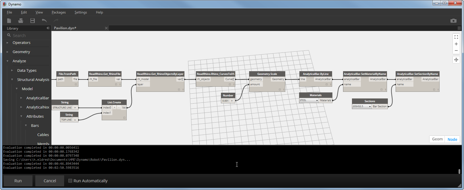
This is the Dynamo definition to get data from Rhino using Rhynamo and then into Robot using the new plugin.
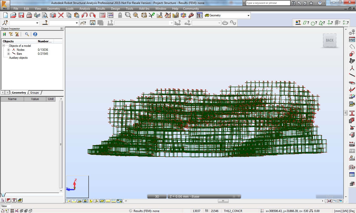
and finally the Pavilion structure in Robot!
The idea of being about to manipulate Robot geometry and get results directly in Dynamo is rather appealing.
It took me a while to work out what was going on but once I got it, it was really quite simple. Like all good little engineers, I started off by making sure it was doing what I thought it should, but this didn’t quite go to plan, so here is a brief run down of the good, the bad, and the ugly:
The Good
- Being able to get geometry directly into an analysis package using something like Dynamo is immense.
- Data can be updated and re-run without starting from scratch.
The less good
This is a really early release so I don’t want to be too critical as I would love for this to be developed further by the authors. However:
- You can’t currently use the Robot plugin if you launch Dynamo inside Revit, however I guess if you wanted to go directly from Revit to Robot you would use the link to achieve this rather than going through Dynamo…
- So far the functionality is limited – you have to apply loads and combinations etc. inside Robot.
- There are a few known issues at the moment. For example, my simply supported beam test was a bit of a failure because the programme currently uses an even number of mesh nodes to calculate the beam results, meaning it doesn’t actually calculate the result in the centre of the beam!
The Summary
I like that Autodesk are going down this route. Dynamo is a massively powerful tool and being able to use it to manipulate data in an analysis package is excellent. Personally I’m not a massive fan of Robot – I’ve never used it in earnest and I find it quite difficult to perform relatively simple tasks. However, this all goes to make the potential of this plugin even better. Imagine being able to use Robot to do your analysis within the Dynamo environment without actually having to use Robot!
My hopes for the future:
- The ability to apply loads and combinations inside Dynamo.
- The ability to extract data from a Robot model with Dynamo – e.g. access to the data and results from an existing model that is open in Robot regardless of how it was created.
So, if you are a Robot user, or even if you aren’t, I recommend taking a look at this plugin. Remember to bear in mind that it’s early in development, but there’s nothing to stop you poking around and getting involved in the development.
Check it out here: Robot Structural Analysis for Dynamo.
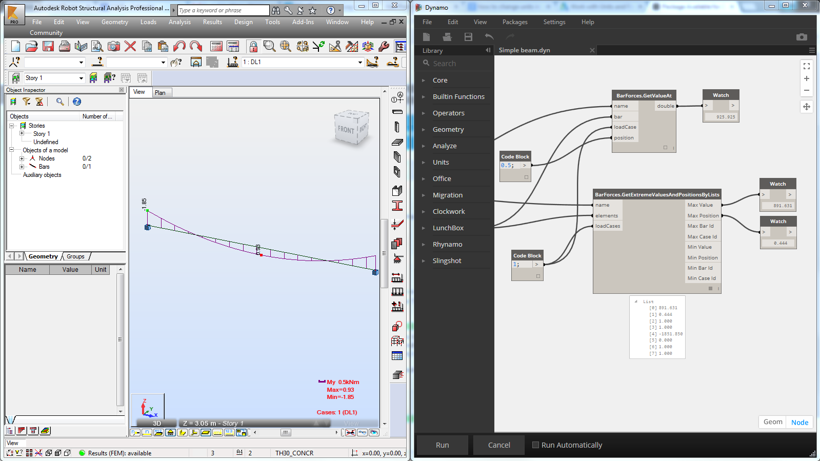
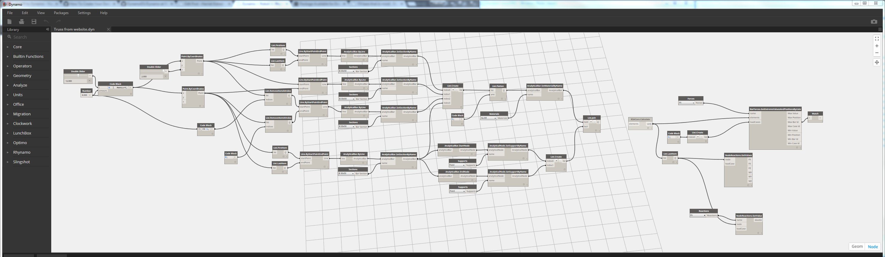
Here are a couple of examples:
This is a screenshot of the example from the Autodesk website, only slightly more legible than in their video.
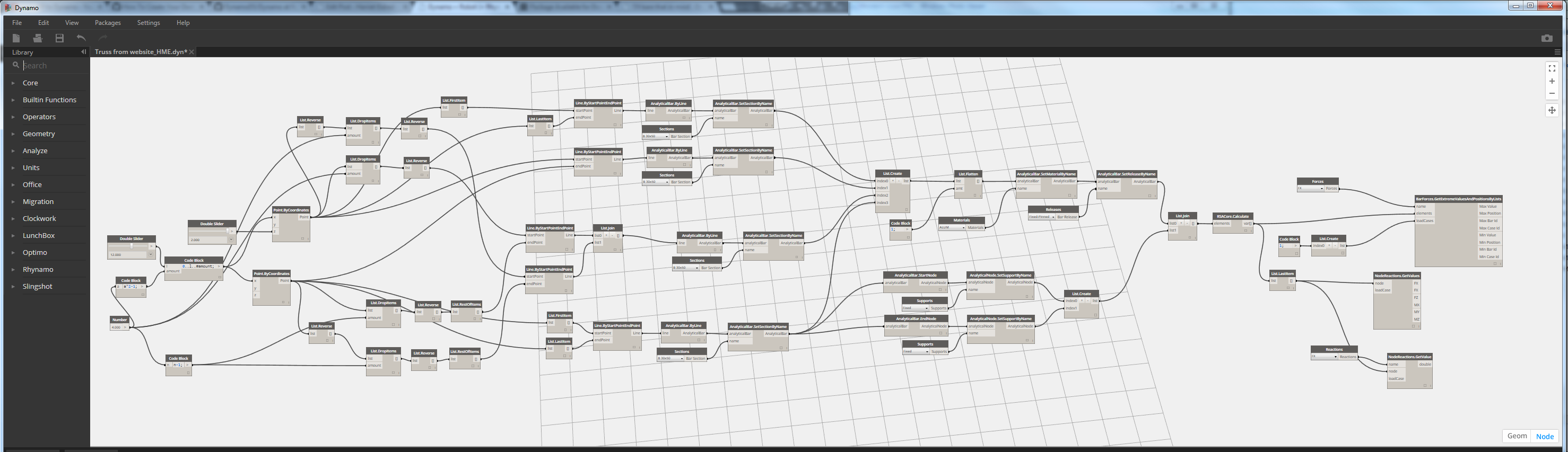
And here is my version of it, with a few tweaks to make it into a Pratt truss.